


 382 / 392

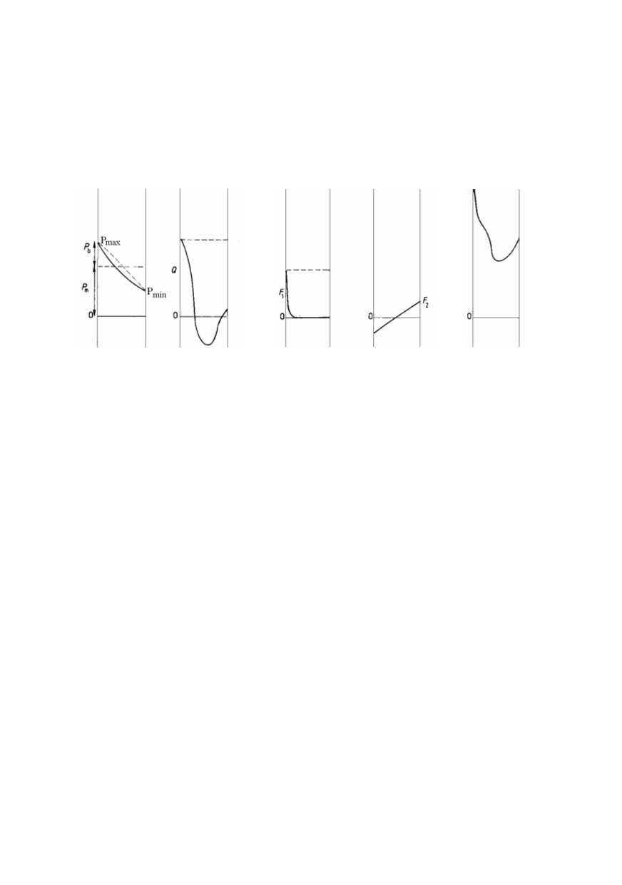
not only about the stress distribution, but also about the division of loading into primary
and secondary loading. Primary stresses mainly occur due to exterior loading and
moments, while secondary stresses are most frequently the result of effects of non-
uniform heating and cooling, e.g. welding–induced stresses that are localized and self–
balancing. Unlike secondary ones, primary stresses may lead to yield fracture, if suffi-
ciently strong. Secondary stresses contribute to fracture, if tensile, with sufficiently high
values and close to a crack.
P
max
P
min
a) primary, b) secondary, c) irregular distribution, d) non-axiality, e) total stress
Figure 6. Schematic presentation of stress distribution across the section
3. EXAMPLES OF STRUCTURAL INTEGRITY ASSESSMENT
3.1. Pressure vessels at hydroelectric power plant ‘Bajina Bašta’
This example is a typical problem if regular control of NDT reveals ‘unacceptable’
defects according to standard JUS ISO 5817
[
12
]
, as was the case with welded joints of
vessels for compressed air in hydroelectric power plant ‘Bajina Bašta’
[
21
]
.
Thus, e.g., the vessel No. 970 had two defects marked as ‘unacceptable,’ one of which
from the photo 970-64 (see Fig. 7), was again ultrasonically examined, which definitely
confirmed incomplete penetration 60 mm long and 2 mm wide. By defect length, in this
case, is to be understood the dimension in the direction of welded joint (longitudinal joint,
photo No.64, near the upper circular seam, Fig. 7), while the width of the defect is its size
in the direction of weld thickness. This defect was chosen as one of three ‘critical,’ both
because of dimensions and location. Namely, as far as dimensions are concerned, it was
the largest defect, and most dangerous because of its location, as it spread near the change
from cylindrical shell to torus–spherical dish cover, where local bending exists.
Vessel No.971 had 11 defects marked unacceptable, according to Report No.2/98 of
Goša Institute, among which defect from Photo No.971-57 was chosen as critical, the
lack of side wall fusion 10 mm long, located in central circular welded joint (Fig. 7).
Detailed ultrasonic inspection did not reveal this defect, but it was still taken into account.
Vessel No.973 had one defect marked as unacceptable. In comparison with defects in
the two above specified vessels, this one was less dangerous, both in size and location
(circular welded joint).
Vessel No.974 had 3 defects marked as unacceptable, according to Report No.5/98 of
Goša Institute. Visual control showed the three defects were in fact defects in shape, i.e.
caused by the lack of fusion between two passes, or interpass cold lap. As those three
defects were located on the circular joint, they were under relatively small influence of
stress, so that their effect on vessel safety was negligible. Besides, those three defects
378