


 381 / 392

2.3. The PD6493 procedure
The original PD6493 procedure
[
19
]
was based on designed CTOD curve. This meth-
odology had a few disadvantages: e.g. the equation for crack growth driving force was
mainly empirical and had varying level of conservative approach. Corrected equations for
the crack growth force became available with R6 and EPRI procedures, while the pro-
jected CTOD curve was already widely applied. Thus in 1991, the PD6493 was modified
[
20
]
, so that previous solutions remained (in level I), while simultaneously, improvements
were introduced (levels II and III). What all three levels of PD6493 have in common is
the method of determination of stress state and crack size. The latest version from the
year 1999 is BS 7910:1999,
Guidance on methods for assessing the acceptability of flaws
in metallic structures
(incorporating Amendment 1).
2.3.1. Crack size
In order to be able to analyze a crack, one should present it in some of the forms for
which analytical solutions do exist. Cracks are divided into passing-through and partially-
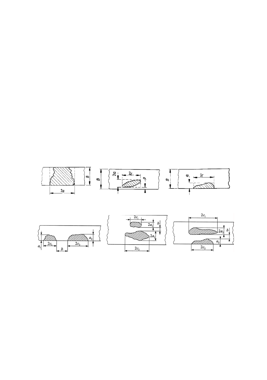
passing, the latter being divided into surface and hidden types, Fig. 4. If there are more
cracks, the increase of stress intensity factor should be taken into account, while at very
close distances the cracks join into a single one, Fig. 5. The procedure of crack analysis
also includes its projection in the plane normal to the direction of main stress, and the
description of a rectangle, the dimensions of which are taken as its basic dimensions.
a)
b)
c)
Figure 4. Cracks: a) passing through, b) partially passing hidden crack,
c) partially passing surface crack
a)
b)
c)
Figure 5. Reduction of cracks to one: a) 2 surface cracks, b) 2 hidden cracks, c) 1 hidden, 1 surface
b
<
c
1
+
c
2
⇒
a
= max(
a
1
,
a
2
)
b
≤
a
1
+
a
2
⇒
a
=
a
1
+
a
2
+
b
/2
b
≤
a
1
+
a
2
⇒
a
= 2
a
1
+
a
2
+
b
2
c
= 2(
c
1
+
c
2
) +
b
2
c
= max(2
c
1
, 2
c
2
)
2
c
= max(2
c
1
, 2
c
2
)
2.3.2. Stress state
In considering the stress state on the location of a crack, the following stresses (the
sum of which makes representative total stress) are taken into account, Fig. 6:
–
membranous stress,
P
m
, as a component of uniformly distributed primary stress;
–
bending stress,
P
b
, as a component of primary stress, varying across section thickness;
–
secondary stress,
Q
, as a self-balancing stress, e.g. thermal and residual stresses;
–
stress increase,
F
, on locations of local discontinuities (irregular shape or non-axiality).
Analytical solutions for plates and cylinders with a partially-passing surface crack
correspond to linear distribution of stresses across the thickness on which tensile and
bending stresses are defined as
P
m
= (
P
min
+
P
max
)/2 and
P
b
= (
P
min
–
P
max
)/2, where
P
min
and
P
max
are minimal and maximal stresses in the section, Fig. 6a. Care should be taken
377