


 388 / 392

Considering the conservative approach in the analysis of critical failures, crack III is
assumed to have 30 mm depth over the entire observed length. In this case the problem
should be considered in the section oriented transversally to the longitudinal direction of
the vessel, where the curvature effect is ignored and quite justifiable for 50 mm thickness
and 2400 mm diameter. The analysis becomes two-dimensional (plain strain) and the
problem is considered as a plate under tension with an edge crack. If the remote stress is
assumed to be the sum of circumferential stress induced by internal pressure (‘boiler for-
mula’) and the residual stress in the weld centre, the stress intensity factor is as follows:
I
6 1200
1.12
1.12
200 30 3741 MPa mm
50
R
pR
K
a
t
σ
π
π
⋅
⎛
⎞
⎛
⎞
=
+
=
+
=
⎜
⎟
⎜
⎟
⎝
⎠
⎝
⎠
(12)
In case that the residual-stress effects are ignored, the following is obtained:
I
6 1200
1.12
1.12
30 1565 MPa mm
50
pR
K
a
t
π
π
⋅
⎛ ⎞
⎛
⎞
=
=
=
⎜ ⎟
⎜
⎟
⎝ ⎠
⎝
⎠
(13)
which is close to brittle fracture (ratio
K
I
/
K
I
c
= 0.99 shows there is practically no reserve
regarding the risk of brittle fracture, not even if residual stresses are ignored. In the net
section stress
σ
n
= 2.5
pR/t
+
σ
R
, where factor 2.5 is taken into account because of section
weakening from a 30 mm long crack in 50 mm thickness. Thus, the following is obtained:
2.5
2.5 6 1200 200
50
2
2
0.97
500 650
R
n
R
F
eH M
pR
t
S
R R
σ
σ
σ
⋅ ⋅
+
+
= =
=
=
+
+
(14)
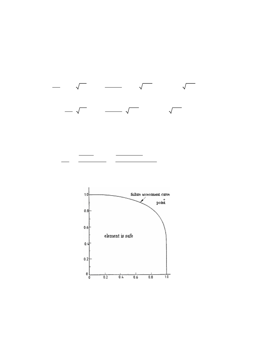
Based on values obtained for
K
I
/
K
I
c
and
σ
n
/
σ
F
, it is obvious that the point (0.99; 0.97)
is located deeply within the unsafe region, Fig. 13.
K
r
S
r
Figure 13. Failure Analysis Diagram (FAD) for the considered pipeline crack
The calculation of stress state using the finite element method (FEM) is made based
on the model shown in Fig. 14 (a quarter of inserted pipe). The results of analysis pre-
sented in Tab. 1 show that the collar decreases stresses from 144 MPa to 80 MPa, in the
region of pipe parts 250 mm away from the middle of the collar, which corresponds to the
location of joints with cracks. However, even with so reduced operating stress, the corre-
sponding point in FAD drops into an unsafe region, as the value for
S
r
modifies to 0.7,
while the value of
K
r
remains unmodified (0.99). However, one should have in mind that
384