


 385 / 392

cylindrical part of the vessel, since in the torus area adjacent to the cylindrical part the
stress is pressure, and not dangerous for crack growth. Thus, non-symmetry in the
problem, caused by the location of crack is ignored, and same as in the previous case. If
the sum of longitudinal stress, caused by internal pressure (‘boiler formula’), and trans-
versal residual stress in the centre of the seam is assumed to be the remote stress, than the
following is obtained for stress intensity factor:
I
7.8 979 200
515 MPa mm
2
84
R
pR K
a
t
σ
π
π
⋅
⎛
⎞
⎛
⎞
= +
=
+
=
⎜
⎟
⎜
⎟
⎝
⎠
⎝
⎠
(7)
which is 32% of the critical value (
K
I
c
= 1580 MPa
√
mm), and does not threat the vessel.
For twice this crack length,
K
I
= 728 MPa
√
mm = 45%
K
I
c
is obtained.
Figure 9. Section scheme in which crack No.978-14 is analyzed
Defect No.971-57 (lack of penetration, 10 mm long, in a circular weld at the middle of
the vessel) has from the very beginning been presented as a passing-through crack, as the
other dimension remains unknown. The data important for the analysis are as follows:
–
pressure geometry (thickness
t
= 50 mm, mean diameter
D
= 2075 mm);
–
crack geometry (10 mm long, direction–along seam, location–circular weld metal in
the middle of the vessel, far from the openings;
–
loads–internal pressure
p
= 81 bar, residual stress
σ
R
= 175 MPa – transversal to weld,
away from weld centre, based on experience with similar material and vessel
[
22
]
.
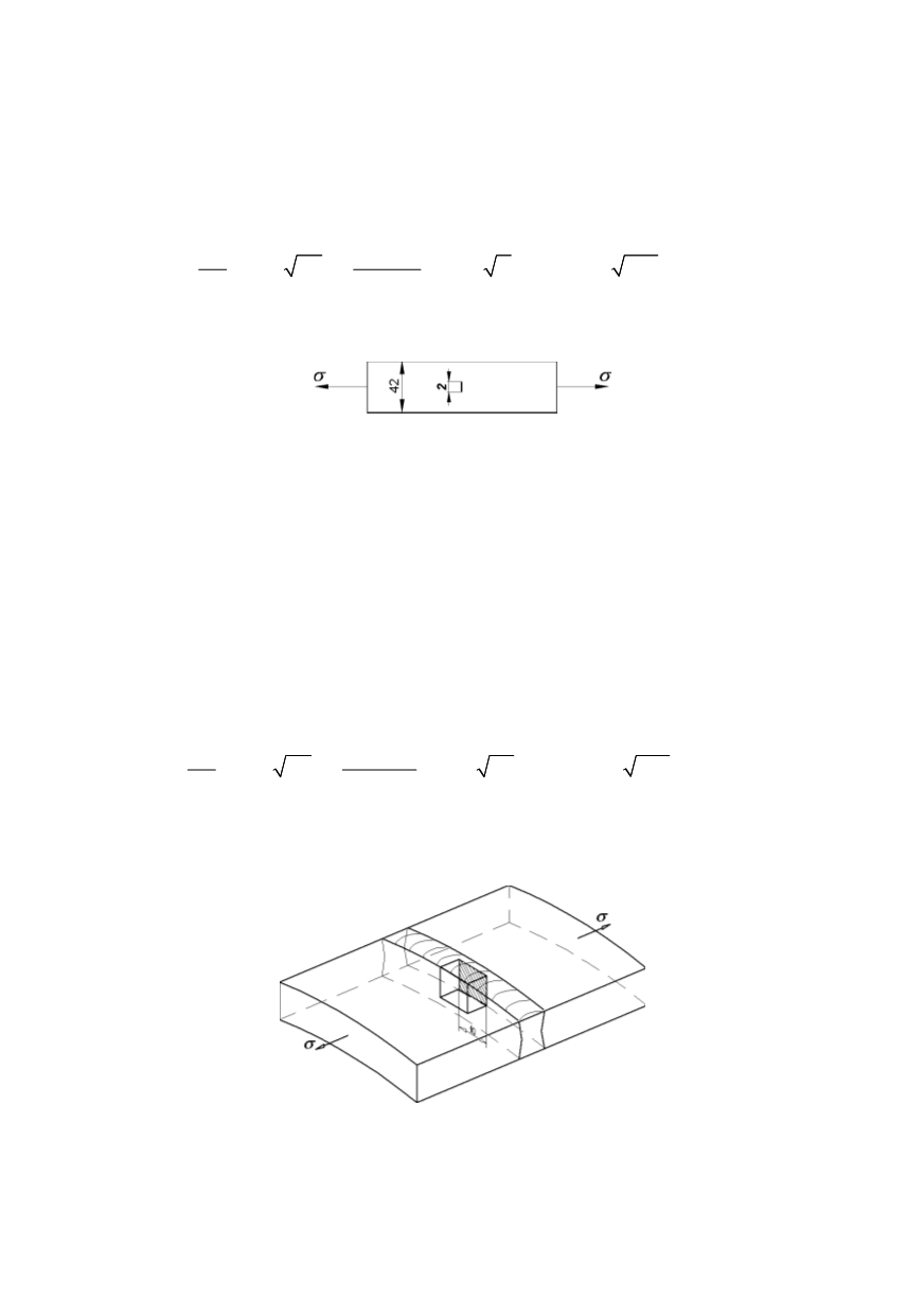
As in the previous case, the problem is presented by a plate under tension, not in the
cross section, but as a “separate” part of the cylinder, Fig. 10. If the remote stress is
assumed as a sum of the longitudinal, pressure induced stress (“boiler formula”), and the
transversal residual stress, away from the weld centre, the stress intensity factor is:
I
8.1 1075 175 5 1039 MPa mm
2
100
R
pR K
a
t
σ
π
π
⋅
⎛
⎞
⎛
⎞
= +
=
+
=
⎜
⎟
⎜
⎟
⎝
⎠
⎝
⎠
(8)
which is 66% of critical value (
K
I
c
= 1580 MPa
√
mm) and does not threat the vessel. Even
if one assumes twice the crack length, the stress intensity factor (
K
I
= 1465 MPa
√
mm for
2
a
= 20 mm) remains below critical value (92%).
Figure 10. Cylindrical part scheme in which crack No.971-57 is analyzed
Further analysis includes plastic material behaviour, i.e. the application of FAD. In
that case the
K
R
parameter has already been defined: 0.59 for defect No.978-14 and 0.92
for defect No.971-57. For evaluation of the
S
R
parameter, one should define the stress in
381