


 387 / 392

establish whether a component is fracture-safe or not, on condition that the geometry and
loading are presented in a conservative way. On the other hand, if the integrity cannot be
proved, this does not mean that the component is useless, but that additional, more
complex analyses are necessary.
3.2. The pipeline at hydroelectric power plant ‘Perućica’
During the period from 1995 to 1996 the pipeline was subjected to inspection a few
times, using various methods of non-destructive testing which, among others, revealed
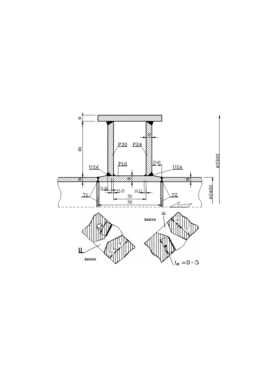
longitudinal defects (cracks) in longitudinal welded joints II and III, where bent sheet
pieces were inserted on the part of increased thickness (50 mm), Fig. 12a. Having in mind
the dimensions of cracks, the crack in the joint III, Fig. 12b, was taken for analysis, as
more dangerous.
383
a)
b)
c)
Figure 12. Detail of the pipeline (a) with cracks in joints II (b), and III (c)
The crack III is presented as a surface crack, partially passing through weld thickness.
The data relevant to the analysis are:
–
pipeline geometry (thickness
t
= 50 mm, diameter
D
= 1200 mm);
–
material of the vessel cylindrical part – CRN 460 (NIOVAL 47, low-alloyed steel of
increased strength);
–
crack size (450 mm long, 0–30 mm deep, direction–along weld, location–fusion zone);
–
loading (internal pressure
p
= 6 MPa, circumferential stress
σ
t
=
pR/t
= 144 MPa, resid-
ual stress
σ
R
= 200 MPa – maximum value–transversal to weld;
–
weld metal fracture toughness, i.e. of heat affected zone (HAZ), minimum value
1580 MPa
√
mm (50 MPa
√
m), and based on experience with the similar base metal.