


 330 / 392

Tanaka [13] carried out experiments on cyclically loaded sheets of pure aluminium
with initial cracks inclined to the tensile axis. As a by-product, the experiments formed
the basis for a crack propagation law
(
)
m
eq
da C K
dN
= ∆
(20)
where
4
4
I
II
(
8 )
eq
K K K
∆ = ∆ + ∆
1 4
(21)
The above equation was developed on the assumptions that
a) plastic deformation due to cyclic tension and transverse shear are not interactive, and
b) the resulting displacement field is the sum of displacements from the two modes.
3. NUMERICAL EXAMPLES FOR CALCULATION OF STRESS INTENSITY
FACTORS
In this section, several examples of stress intensity factor calculation in case of crack
under the assumption of plane strain and plane stress two-dimensional elasticity are pre-
sented. At the beginning a simple example of an edge crack is chosen to demonstrate the
robustness of the above technique, and then results for more complicated geometries are
presented. Results obtained with PAK will also be compared with results obtained by
using the COSMOS
program.
Example 1
In this example the stress intensity factor is determined for both modes of fracture
(opening
K
I
and shear
K
II
) for a rectangular plate with an inclined crack edge subjected to
uniform uniaxial tensile loading at the two ends.
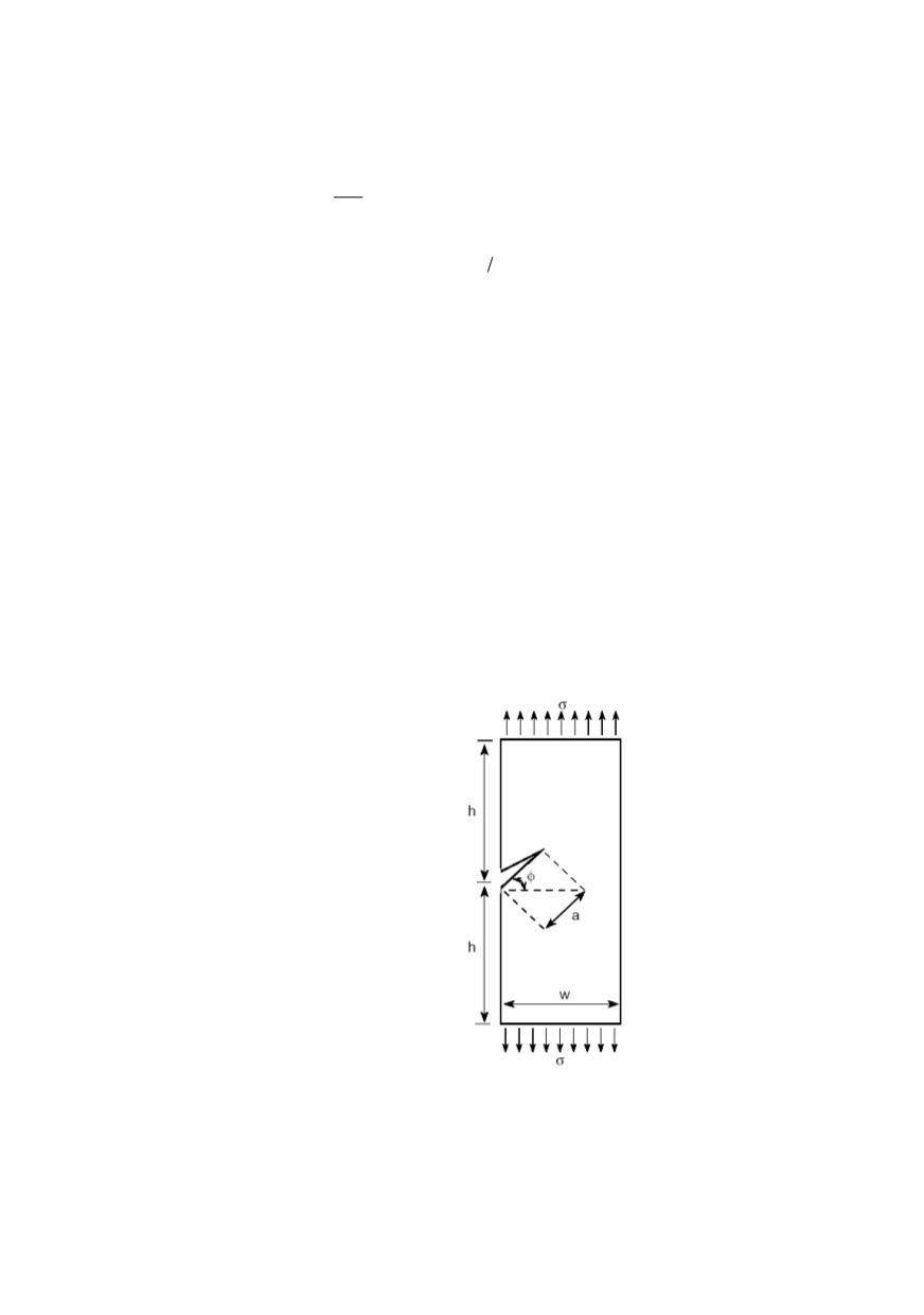
Known data are given in Fig. 4.
σ
= 1 psi
h
= 2.5 in
W
= 2.5 in
a
= 1 in
E
= 30
×
10
6
psi
ν
= 0.3
φ
= 45°
thickness = 1 in
Figure 4. Model for testing
The full part has to be modelled since the model is not symmetric with respect to the
crack. There is no restriction in proposed FE models, so that mesh can be either
symmetric or non-symmetric with respect to the crack. However, the nodes in the two
sides of crack cannot be merged in order to model the rupture area properly. Figure 5
shows the first and second region of integration for equivalent domain integral.
326