


 333 / 392

Example 3
In this example [14], a 3-D analysis of the turbine housing is carried out. Using the
original design documentation, the 3-D geometrical model of the turbine is generated. In
this 3-D object, cracks with different lengths (90–375 mm) and depth (20–40 mm) are
assumed and modelled. Calculations are performed to investigate the influence of crack
length and depth on the value of maximum effective stress, as well as on the value of
stress intensity factor.
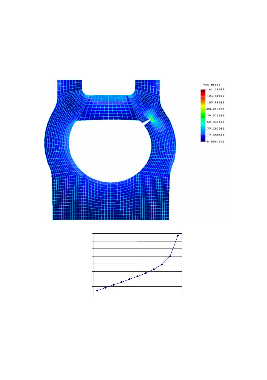
Figure 7. Effective stress field for crack length 30 mm
6
8
10
12
14
16
18
20
22
20 25 30 35 40 45 50 55 60 65 70
Figure 8. Relationship between stress intensity factor
K
I
and crack length
Boundary conditions: Lower part of the turbine housing has an axial plane of symme-
try so that the 2-D model corresponds to the cross-section of that plane and the solid body
of the housing.
329
For calculation of the temperature field, boundary conditions of thermal conduction
according to Fig. 6 are used. In order to reduce the number of elements in the 3-D grid,
the critical quarter of the turbine is modelled. It is worth to emphasize that the cracks are