


 327 / 392

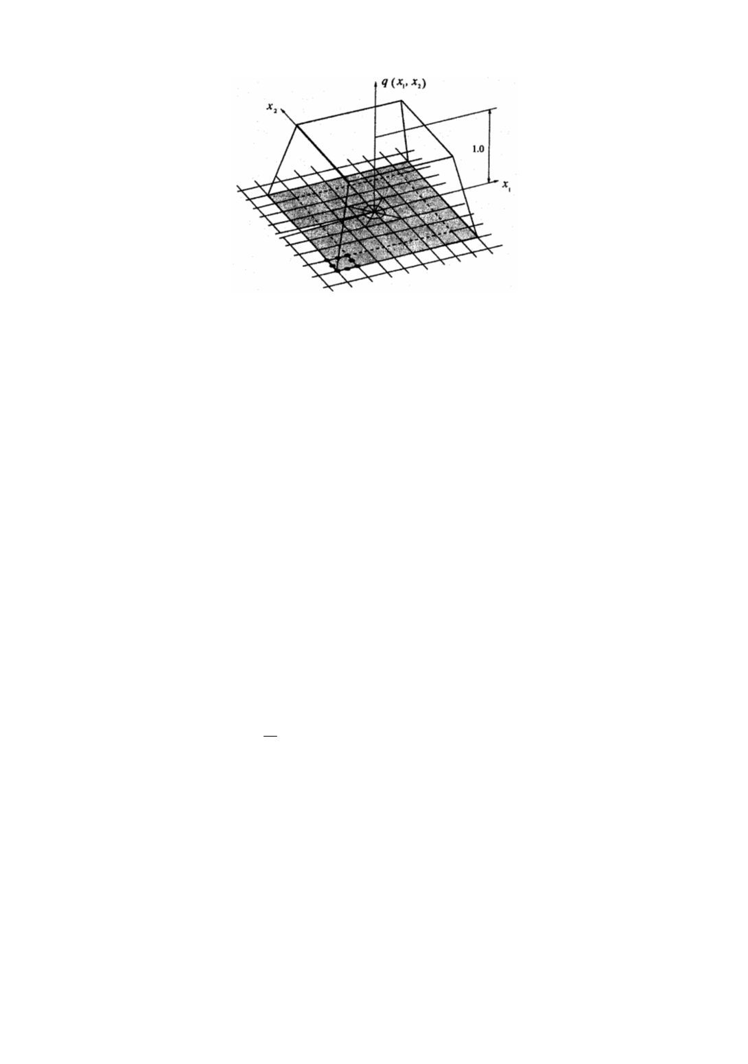
Figure 2. Weight function (
q
function)
Taking the limit
Γ
S
→
0 leads to
0
0
0
,,
,,
0
0
,,
,,
0
0
lim
(
)
lim
(
)
lim
(
)
lim (
)
S
S
S
S
S
S
S
kj
ij i k j
kj
ij i k j
kj
ij i k j
kj
ij i k j
W u m qd
W u m qd
W u m qd
W u m qd
δ
σ
δ
σ
δ
σ
δ
σ
+ −
+ −
+ −
Γ →
Γ →
Γ +Γ +Γ −Γ
Γ +Γ +Γ −Γ
Γ →
Γ → Γ
Γ +Γ +Γ
−
Γ =
−
=
−
Γ −
−
Γ
∫
∫
∫
∫
Γ =
i k j
(7)
Since
q
= 0 on
Γ
0
and the crack faces are assumed to be traction–free, the above equa-
tion becomes
,
0
0
lim lim (
)
S
S
k
kj
ij
J
W u m q
δ
σ
Γ → Γ → Γ
= − Ψ =
−
Γ
∫
d
(8)
Applying the divergence theorem to Eq. (8), one can obtain the following expression
,
,
,
,
(
)
(
)
k
ij i k
kj
j
ij i k
kj j
A
A
J
u W q dA u W qd
σ
δ
σ
δ
=
−
+
−
∫
∫
A
(9)
where
A
is the area enclosed by
Γ
. Note that the second term in the above equation must
vanish for linear-elastic materials [4,5,6], and it follows
,
,
(
)
k
ij i k
kj
j
A
J
u W q d
σ
δ
=
−
∫
A
(10)
This expression is analogous to the one proposed for a surface integral based method
to evaluate stress intensity factors [4].
In 3D case the
J
–EDI integral is converted into a volume integral [5–8] as
,
,
1 (
)
k
kj
ij i k
V
j
J
W u q
f
δ
σ
= −
−
∫
dV
(11)
where
f
= (2/3)
∆
with
∆
being the thickness of the 3D element in the crack front direction.
1.2. Numerical evaluation of the J integral
The
J
–integral evaluation in the PAK program
is based on the domain integration
method described above. A direct evaluation of the contour integral is not practical in
finite element analysis (FEA) due to difficulties in defining the integration path
Γ
. The
conversion of the contour integral to the domain integral is exact for the linear elastic case
and also for the nonlinear case, if unloading does not occur [4].
323
Since FEM calculations of displacements, strains, and stresses are based on the global
coordinate system, the (
J
k
)
global
is evaluated first and then, if needed, transformed into
(
J
k
)
local
. The above expressions are represented by local coordinates
x
k
, (
k
= 1,2), which
can be expressed in terms of global coordinates
X
i
by the transformation: