


 320 / 392

The second parameter
L
r
is defined by
316
Y
F
r
L
F
=
(26)
where
F
Y
is the yield load of the cracked configuration.
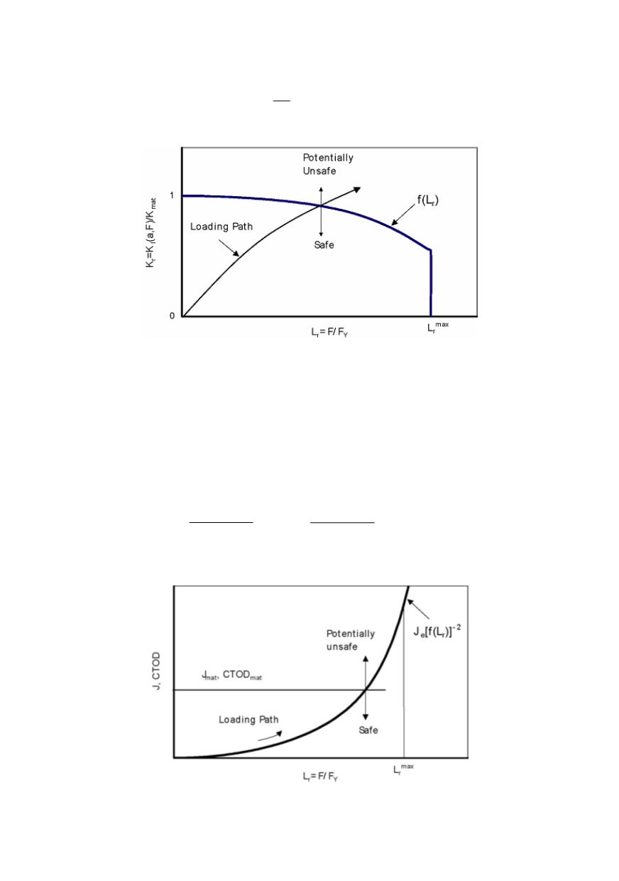
Figure 16. Failure assessment based on a FAD philosophy
1.9.2. CDF route
ent (CTOD =
δ
) is determined, which characterises the stresses and
str
where
J
e
and
δ
e
are the elastic values of the crack tip parameters which can be
from the stress intensity factor
K
(
a
In the CDF route (Fig.
opening displacem
17), an applied parameter such as the
J
–integral or crack tip
ains ahead of the crack tip in a specimen or component:
[
]
2
( )
e
r
J J f L
−
=
or
[
]
2
( )
e
r
f L
δ
δ
−
=
(27, 28)
deduced
I
[
]
,
F
) as
2
I
( , )
e
K a F
J
=
or
[
]
2
( , )
e
K a F
δ
E
′
I
Y
E
σ
=
′
(29, 30)
with
E
′
being Young’s modulus in
stress and
E
/(1 –
ν
2
) in plane strain. The
ν
is Poisson’s ratio.
plane
quantity
Figure 17. Failure assessment based on the CDF philosophy
(The function
f
(
L
r
) is identical for the FAD and CDF routes)