


 316 / 392

sustainable stress. This is supposed to represent the attainment of net section yielding, i.e.
each point in the ligament ahead of the crack is supposed to have just reached the yield
condition. This is correct for the ideally plastic material, however, for hardening materials
some points are still under elastic deformation condition. Therefore, the thus determined
value of
F
Y
represents a lower bound to the real yield load of component materials.
Within the SINTAP procedure a compendium of limit loads is provided. Other compi-
lations are available in literature, e.g. in [11]. For cases, which are not covered by this
compilation, conservative estimates are possible based on substitute geometries. In such
cases the stress profiles in the components without crack are taken as input information.
Within the SINTAP procedure a loading parameter
L
r
is used which is defined as the
ratio of the applied load
F
and the limit load
F
Y
, or respectively as the ratio of an applied
net section stress
σ
ref
and the yield strength of the material,
σ
Y
, (Fig. 14):
r
Y ref
L F F
σ
σ
= =
Y
(8)
the latter being given as
σ
Y
=
R
eL
for materials with, and
σ
Y
=
R
p
0.2
for materials without a
Lüders plateau.
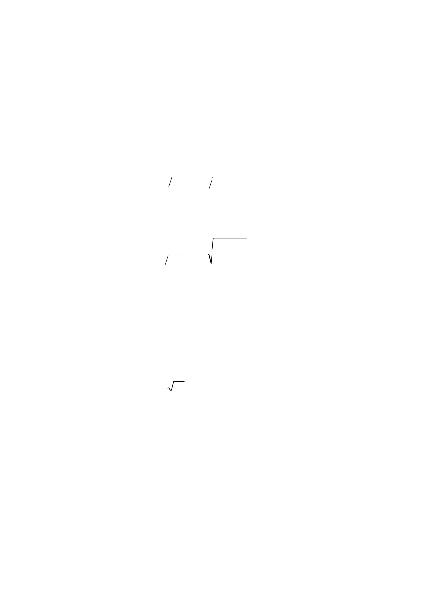
The reference stress of the plate geometry considered within this paper can easily be
determined as
2
2
1
1 (2 ) 3 9
b
b
ref
m
c W
σ
σ
σ
σ
⎧
⎫
⎪
⎪
=
+ +
⎨
⎬
−
⎪
⎪
⎩
⎭
(9)
1.6. Stress intensity factor (
K
factor)
As in the case of the limit load, numerous solutions for
K
factors are available in
compendia, e.g. [2,3]. The SINTAP procedure provides its own compilation of such solu-
tions. Stress intensity factors can be determined for single loads such as forces, bending
moments, internal pressures etc., as well as for stress profiles. The latter alternative
allows handling geometrically complex components by using substitute structures, i.e. the
stress profile is determined for the real structure without crack, whereas the determination
of the
K
–factor is based on a simpler geometry like a plate, cylinder, etc. The
K
factor for
the fork in the present paper was determined by
I
( , )
(
)
m m b b
K c F c f
f
π σ
σ
=
+
(10)
where
f
m
and
f
b
are shape functions being defined for a plate with a through crack. They
are
f
m
A
= 1 and
f
b
A
= 1 for point A, and
f
m
B
= 1 and
f
b
B
= –1 for point B.
1.7. Correction function
f
(
L
r
)
Under conditions of small scale yielding (roughly up to 0.6 times the limit load) a
fracture mechanics analysis can be based on the linear-elastic
K
factor. This is, however,
not possible for contained and net section yielding where the plastic zone is no more
limited to a small region ahead of the crack tip. Under this condition any application of
the
K
concept would lead to a significant underestimation of the real crack tip loading in
terms of the
J
–integral or CTOD. Irrespective of this general statement the application of
a formal
K
concept becomes possible when the linear-elastic
K
factor is corrected with
respect of the yield effect. This is essential of the correction function
f
(
L
r
). With respect
of
f
(
L
r
), the SINTAP procedure is structured in a hierarchic manner consisting of various
analysis levels constituted by the quality and completeness of the required input informa-
tion. Higher levels are more advanced than lower levels: they need more complex input
312