


 314 / 392

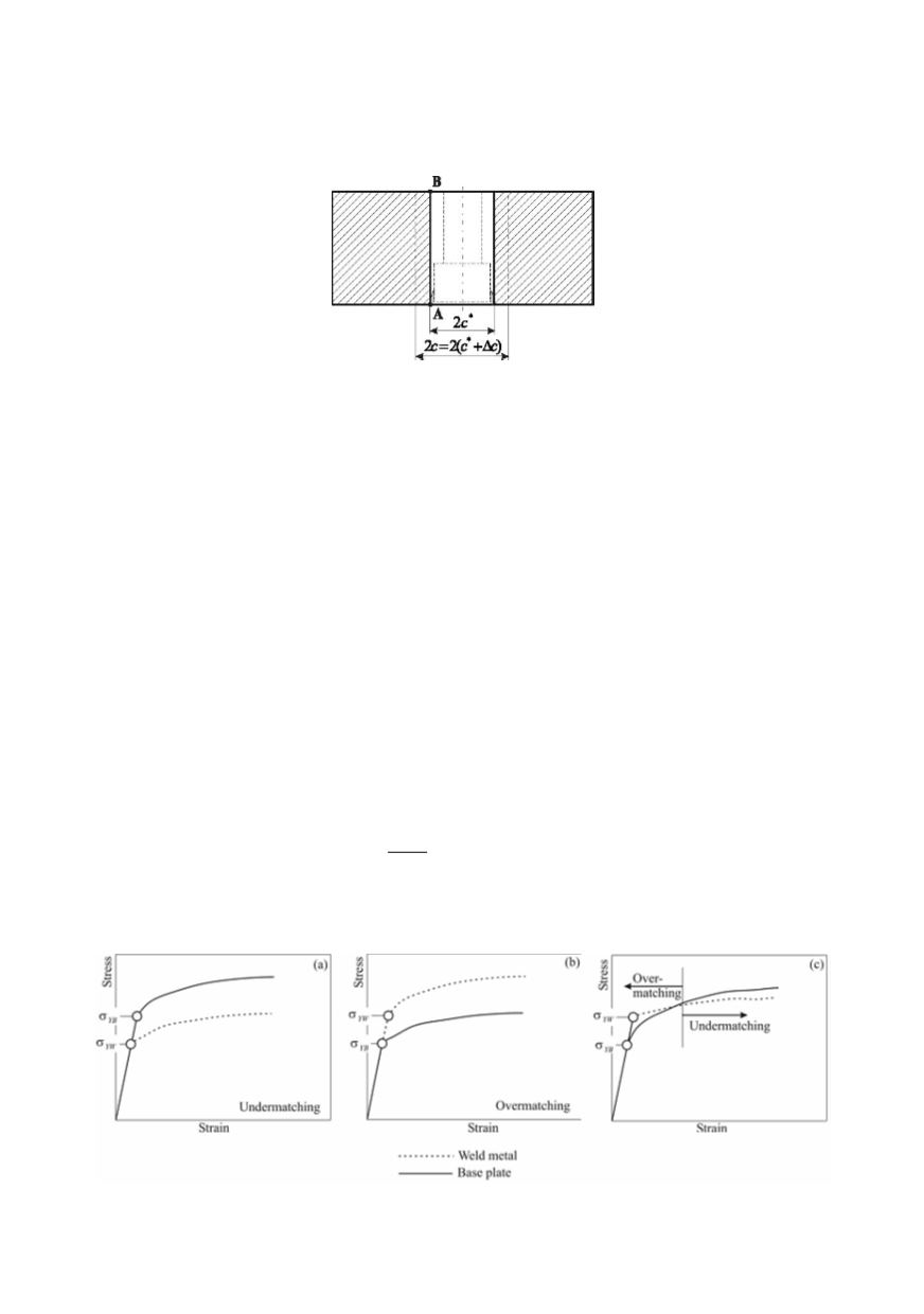
In the present case of fork, the two edge cracks have been substituted by one through
crack with dimensions which include the hole diameter as given in Fig. 11. For simplicity
the crack is assumed to be of constant length, 2
c
, over the wall thickness.
Figure 11. Definition of the idealized crack dimension 2
c
Usually, the crack plane is assumed to be perpendicular to the larger of the two
principle stresses. In some cases, however, a real crack will not grow within this plane
because of mechanical reasons, i.e. both principal stresses are of a magnitude of the same
order, or because of the material heterogeneity. In such cases a more complicated mixed-
mode analysis has to be carried out. In the present case the situation is quite simple
because the maximum principle stress direction is identical to the axis of the fork.
In the flow chart in Fig. 3 the crack dimensions are introduced as input data. Actually,
this refers to a default crack size, which is then varied iteratively. In each iteration step
one should conclude whether the actual crack size is critical or not.
1.4. Homogeneous or strength mismatched configuration
Mismatch of strength means that in the welded joint, the base plate and the weld metal
are of different strength, with the consequence of local strain concentrations within the
weaker area if the yield strength of weld metal differs more than 10% from that of the
base metal; if this difference is bellow 10%, the use of SINTAP procedure for homoge-
neous material (base plate) is recommended. The weld metal is commonly produced with
yield strength,
σ
YW
, greater than that of the base plate,
σ
YB
. In Fig. 12b this case is desig-
nated as OverMatching (OM) with the mis-match factor
M
,
1
YW
YB
M
σ
σ
= >
(6)
UnderMatching (UM) (Fig. 12a) is defined by
1
M
<
(7)
Figure 12. Definition of strength mismatched configuration
310