


 311 / 392

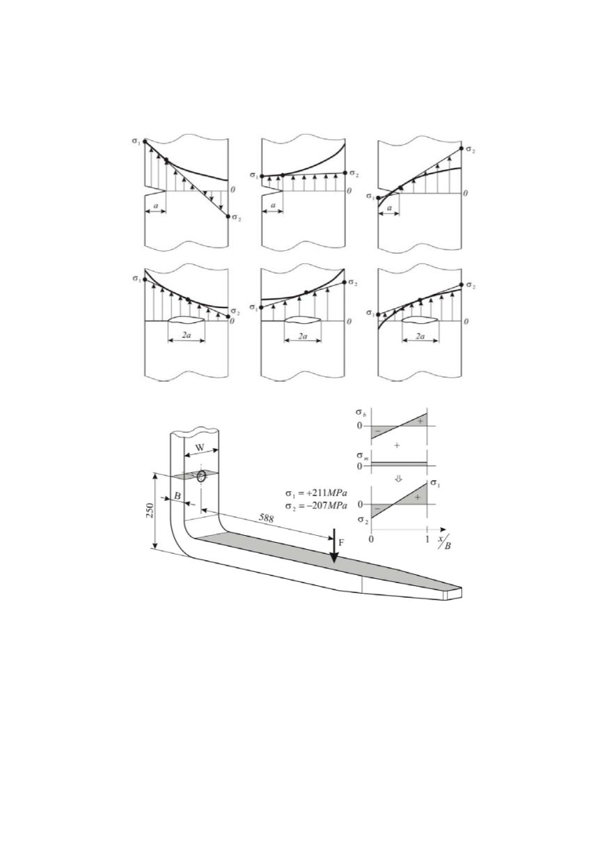
shown in Fig. 7, which is characterized by stress values
σ
1
and
σ
2
at the front and back
surfaces of the plate. Based on these data, a bending stress and a membrane stress com-
ponents are determined as:
σ
b
= 209 MPa;
σ
m
= 2 MPa.
These values correspond to one half of the design nominal load (35 kN) for the fork.
Figure 6. Distribution of membrane and bending stresses through thickness
Figure 7. Stress distribution across the fork section containing the crack (all measures in mm).
Membrane stress component: σ
m
= 0.5(σ
1
+ σ
2
). Bending stress component: σ
b
= 0.5(σ
1
− σ
2
)
In the present case only primary stresses had to be considered. In practice there are
many cases, e.g., weldments – where these have to be completed by secondary stresses. In
general, primary stresses arise from mechanical applied loads including the weight of the
structure whereas secondary stresses are due to suspended stresses. Typical examples of
secondary stresses are welding residual stresses. Secondary stresses are insignificant for
common strength analyses because they are self equilibrating across the section. This is,
however, no longer true when the same cross section contains a crack. In such a case,
secondary stresses can be a major loading component which has to be considered in any
analysis. In SINTAP, secondary stresses are taken into account in determining the
K
factor but not in determining the limit load,
F
Y
, or the degree of ligament plasticity,
L
r
.
307