


 310 / 392

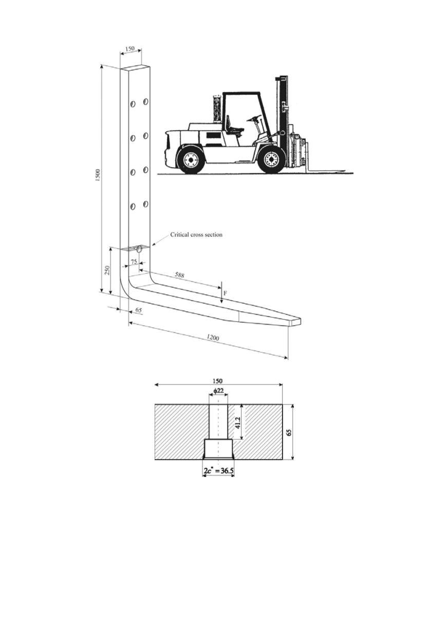
Figure 4. Geometry and dimensions of the fractured forklift (all measures in mm)
Figure 5. Geometry and dimensions of the fractured cross section (all measures in mm)
1.2. Applied load including secondary load components
In the SINTAP procedure the applied load can be introduced as a single load such as a
tensile force, a bending moment, or internal pressure. The stress distribution analysis, i.e.,
determined by finite element method (FEM) is valuable, Fig. 6. Note that such a stress
distribution profile refers to the component without crack. In the considered case of frac-
tured fork, the loading type is predominant bending, that has allowed the application of a
simple analytical model for determining bending stress. However, in order to also consi-
der the membrane stress component, finite element analysis yielded the stress profile
306