


 365 / 392

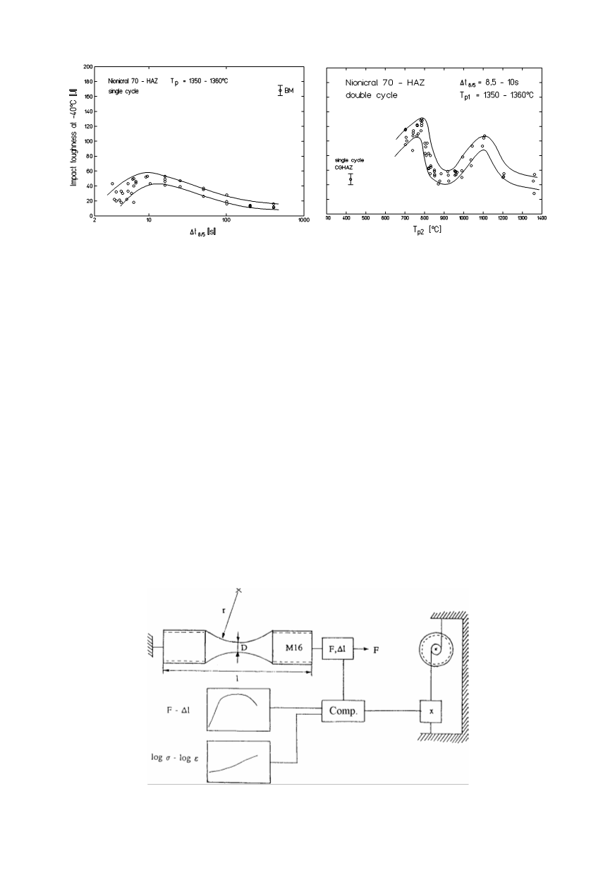
Figure 10. Impact toughness against
∆
t
8/5
for a single cycle CGHAZ (left), and against
T
p
2
for
HSLA structural steel Nionicral 70 (right)
.
D le-cycle HAZ was previously CGHAZ.
)
and
pli-
cat
m
0
m
oub
Measurement of mechanical properties (yield strength and ultimate tensile strength
rheological material properties of different zones of welded joints is pretty com
ed. Standard gauge-length of tensile specimen has be at least 10 times longer than the
diameter. Simulated microstructure exists only in the middle of the sample, therefore
some adapted tensile specimens should be used. An experimental set-up is sketched in
Fig. 11.
Hourglass-shaped specimens were used in reference [13]. The load,
F
, the load-line
displacement,
∆
l
, and circumference,
π
D
, had been measured during specimen loading.
Change of circumference can be used for the determination of decreasing cross-section
diameter
D
. The circumference enabled calculating true strain during tensile testing,
because standard strain measurement in the longitudinal direction of the specimen is not
possible here.
The diagram with load (
F
) transformed into engineering stress (
σ
0
) versus load-line
displacement (
∆
l
) enabled determining ultimate tensile stress,
R
, if the value
σ
is
known. Fracture stress,
σ
f
, is expressed by
σ
0
f
(Fig. 12–top). The engineering strain (
ε
0
) is
calculated via change of specimen’s current diameter,
D
, and yield stress,
R
p
0.2
, on the
basis of
σ
0
p
0.2
(Fig. 12–bottom).
Strength coefficient
A
and plastic strain exponent
n
are determined using logarithmic
dependence of true stress against true strain (Fig. 13).
361
Figure 11. Experimental determination of mechanical and rheological properties
of material with the simulated microstructure