


 359 / 392

2. THERMAL CONDITIONS IN WELDING PROCESS
Structural steels belong to polycrystalline metals. In general, properties of polycrystal-
line metal depend on its microstructure. Microstructure is a function of chemical compo-
sition, thermal history, and starting microstructure. The same situation is with different
zones of welded joints in steels.
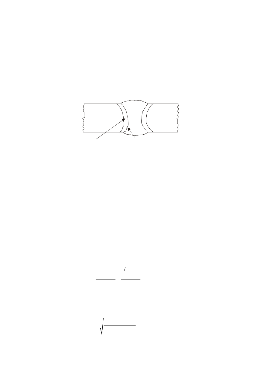
Each fusion welded joint consists of two materials: the weld metal (WM) and HAZ,
whereas, WM is solidified mixture of fused filler and base metal (BM) if welding with
consumable electrodes is applied. HAZ is actually BM in which the microstructure is
altered due to the welding thermal effect. Fusion line defines the limits of both materials
(Fig. 1).
BM
HAZ
WM
fusion line
Figure 1. Specific zones in a fusion welded joint (BM, WM, and HAZ)
Joining by fusion welding can be performed either in a single run (single pass weld-
ing) or using two or more passes to realize the joint (double- or multi-pass welding).
In case of single pass welding, the microstructure of the weld metal is more or less
uniform, but the microstructure of HAZ depends on the peak temperature of the thermal
cycle and its cooling time. The heating sequence of welding cycle is not important, whilst
the sequence of the highest temperatures and the cooling sequence, especially the cooling
rate, are decisive for the final microstructure. The first and second sequences have effects
on grain growth while the second and third sequences – on the micro-constituents that
have been formed [9]. Cooling rate for carbon structural steels is usually expressed as
∆
t
8/5
. This is the cooling time in the temperature range 800–500°C when austenite decom-
poses into microconstituents stable at lower temperatures.
The expressions from reference [10] were used to design appropriate cooling sequence
at a particular point in the vicinity of the heat source during seam welding. Three-dimen-
sional heat flow is assumed.
For defined
∆
t
8/5
and temperature of the material
T
0
(either ambient/preheating tem-
perature or inter-pass temperature) an appropriate net heat input,
Q
, is calculated as:
8 5
0
0
2
1
1
500
800
t
Q
T
T
πλ
∆
=
−
−
−
(1)
where
λ
is the thermal conductivity.
If the peak temperature of the thermal cycle caused by welding,
T
p
, is fixed, the
distance
R
from the point in the HAZ to the line where the heat source is travelling during
a weld-pass deposition can be calculated as:
0
2
(
)
p
Q
R
πeρc T T
=
−
(2)
where
c
and
ρ
are the heat capacity and the density, respectively.
355