


 308 / 392

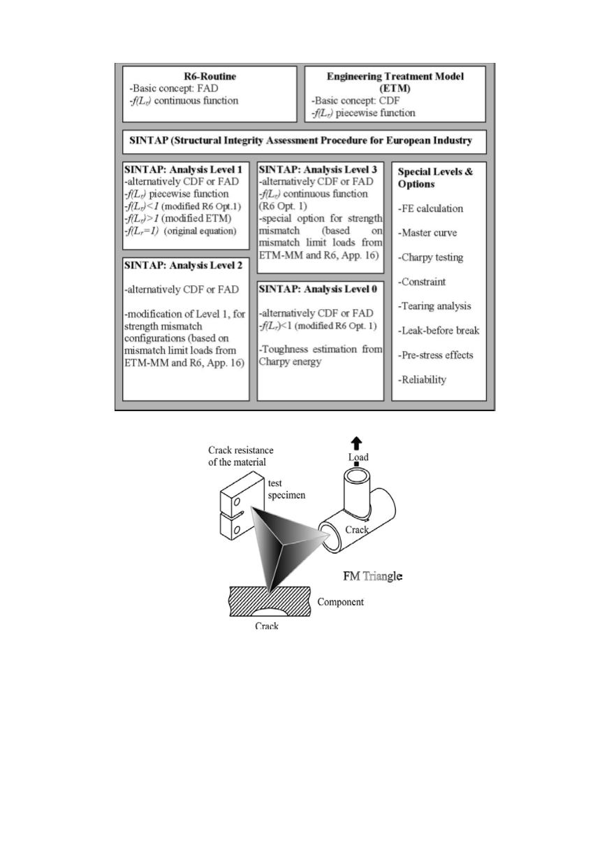
Figure 1. Overall structure of the SINTAP procedure, [9]
Figure 2. Fracture mechanics principles in design
The procedure for determining the critical crack size is illustrated in Fig. 3. Some
basic items of SINTAP application will be addressed following this flow chart. Although
some features and analysis steps shown in the flowchart will not be applied to fractured
forklift analysis, they will be presented briefly because they provide important informa-
tion for many other cases of failure analysis.
In order to determine a critical crack size the following input information is required:
•
geometry and dimensions of the component,
•
applied load, including secondary load components, such as residual stresses,
•
information on crack type and orientation, and
304
•
the stress-strain curve and fracture toughness of the material.