


 305 / 392

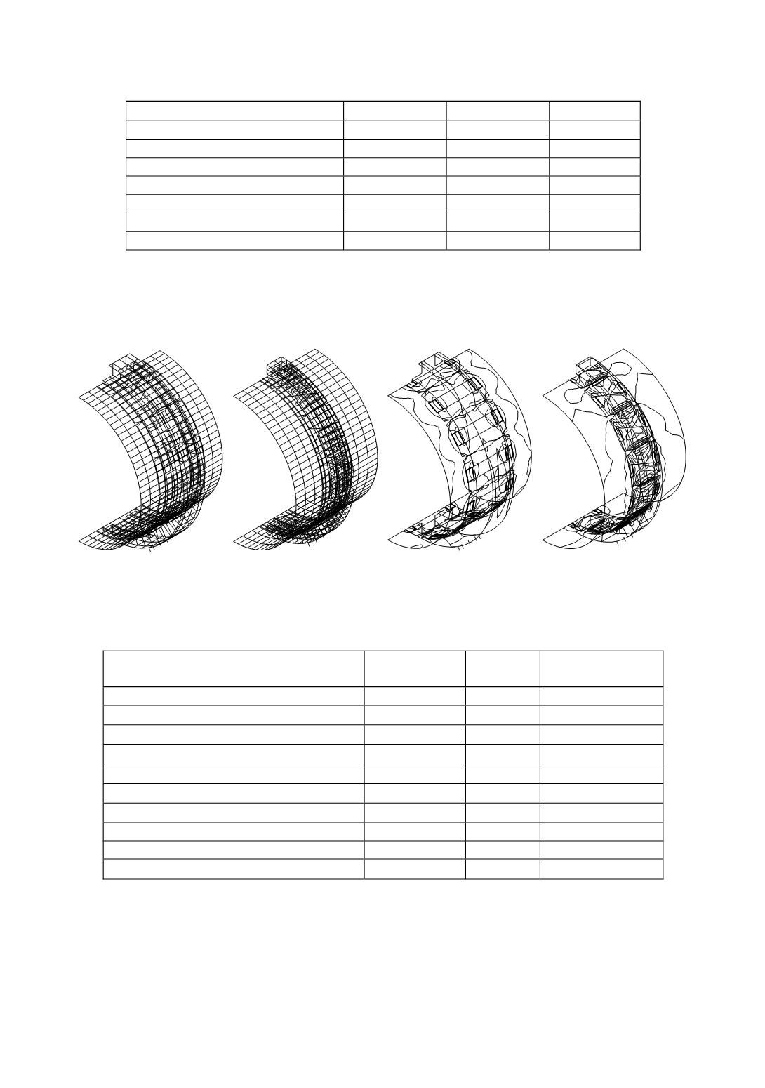
Table 16. Distribution of loading effects
Element
E
d
abs
/E
d
rel
Memb/Bend
σ
/
τ
Shell
10.2/5
27.2/19
37.9/8.3
3.ring
49.5/23.5
6.8/9.6
14.6/1.7
Tooth (Gear), 3.ring
32.8/40.7
0.7/0.1
0.6/0.2
Element, 3.ring
5.3/4.9
5.2/11.3
13.7/2.8
Weld 3.ring.
2.1/25.8
2.6/5.8
7.1/1.3
1 + 2 ring
0.1/0.1
5.6/6.1
9.4/2.3
∑
100/100
48.1/51.9
81.6/18.4
For the verification of obtained results, the results for existing and modified rings are
compared in Fig. 46 and in Table 17 with the results obtained by the company Krupp–
Polysius. It is possible to conclude that the results for the modified model are close to that
of the Krupp–Polysius model.
Modifed model
Krupp–Polysius model
σ
joint
eq
= 0–12.7 kN/cm
2
,
step 1
σ
joint
eq
= 0–12.6 kN/cm
2
,
step 1
Figure 46. Compared modified and Krupp–Polysius models
Table 17. Results of calculation (model, deformation [cm], stress [kN/cm
2
], energy)
Model
Modification
model
Existing
model
Krupp-Polysius
model
Max. deformation
1.66
1.66
1.58
Max.
σ
joint
eq
/
σ
element
eq
12.7/13
13.1/16.6
12.6/17.5
Shell
σ
joint
eq
/
σ
element
eq
4/4.5
13.1/13.8
4/4.3
Weld
σ
joint
eq
/
σ
elem
eq
12.7/13
13.1/13.8
12.6/14.8
Element
σ
joint
eq
/
σ
elem
eq
9/10.5
8/10
12.6/17.5
Ring
σ
joint
eq
/
σ
elem
eq
5/5.1
5/5.7
4.5/4.9
Tooth
σ
joint
eq
/
σ
element
eq
- /2.5
- /3.9
- /3.3
Deformation energy [kNcm]
2400
2460
5330
Membrane/Bending [%]
51/49
43/57
34/66
σ
/
τ
stress [%]
87.5/12.5
87.5/12.5
86/14
REFERENCES
1.
Maneski, T.,
Kompjutersko modeliranje i proračun struktura
, Monography in Serbian, Faculty
of Mechanical Engineering, Belgrade. (1998)
2.
Maneski, T.,
Computer modelling and structural analysis
, Faculty of Mechanical Engineering,
Belgrade. (2000)
301