


 303 / 392

a
1
,
σ
u
/
σ
s
= 6/6.5
a
2
,
σ
u
/
σ
s
=7.5/7.5
a
3
,
σ
u
/
σ
s
= 11/11
a
1
,
f
= 0.544 cm
a
2
,
f
= 0.571 cm
a
3
,
f
= 0.65 cm
Crack
a
1
= 10.7 cm,
f
max
= 0.55 cm
Crack
a
1
= 10.7 cm,
σ
eq
= 0–4.375 kN/cm
2
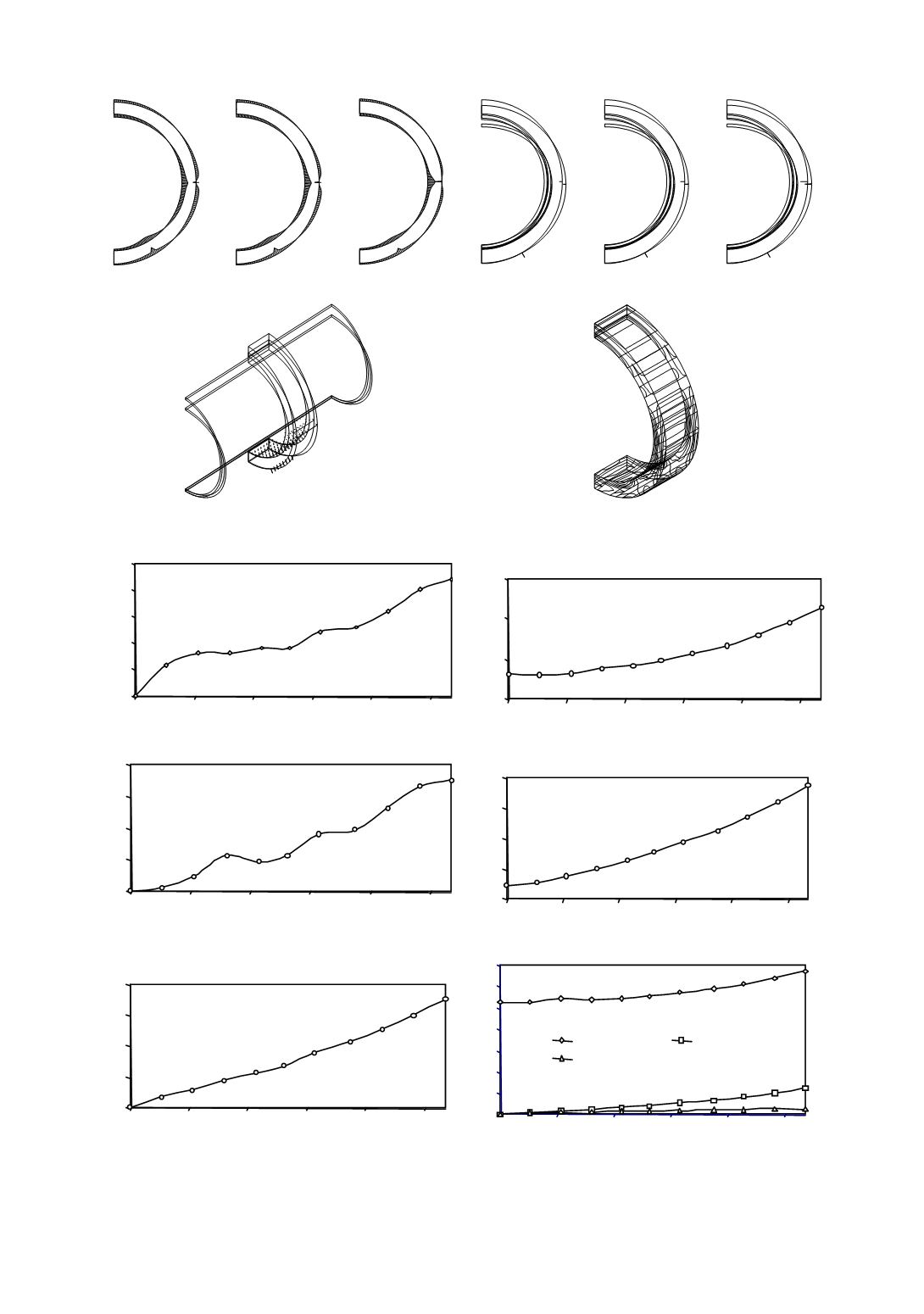
Figure 43. Stress and deformation, for crack lengths
a
1
= 10.7 cm,
a
2
= 15.72 cm,
a
3
= 26.8 cm
0
10
20
30
40
50
0
5
10
15
20
2
Crack length,
a
[cm]
5
300
350
400
450
0
5
10
15
20
25
Crack length [cm]
Increment of the element compliance,
dC/da
Deformation energy,
E
d
0
5
10
15
20
0
5
10
15
20
25
C rack length [cm ]
0
Deformation energy [kNcm]
dC/da
×
10
–7
[cm/kNcm]
Deformation increment [kNcm]
299
10
20
30
40
0
5
10
15
20
25
Crack length [cm]
Deformation energy on
crack tip [kNcm]
Increment of deformation energy,
dE
d
/da
Deformation energy at the crack tip
0
0.5
1
1.5
2
0
5
10
15
20
25
Crack length [cm]
0
1
2
3
4
5
6
7
0
5
10
15
20
25
Crack length [cm]
Max.deformation
CODdeformation
CTODdeformation
product
σ
y
*B
Maximum deformation, COD and CTOD
σ
y
* CTOD [kN/cm
2
mm]
Deformation [mm]
Figure 44. Crack growth effect on the behaviour of different parameters