


 298 / 392

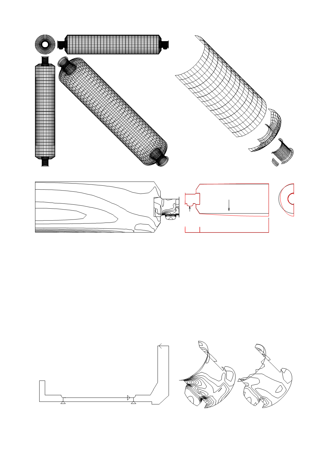
Model of the limestone-mill
f
max
=2.70 cm
Σ
G
i
=640 kN
R
Stress field of sleeve and shell
Model contour, loading and deformation
Figure 31. The analysis for reconstruction of the sleeve of limestone-mill “UNIDIAN”
Considered model variants are: changed sleeve cross-section area and thickness in the
saddle support zone,
δ
1
from 2.75 to 6 cm; and next to this zone,
δ
2
from 4.5 to 7.5 cm
(Fig. 32).
Based on computational results, presented in Fig. 33 and in Table 12, for this type of
support, the thickness of the sleeve cylinder had dominant effect on the stress field. The
stress value had decreased 3 times, the stress concentration is reduced, changes in stiff-
ness are reduced and welding had been performed in the longitudinal direction. Model B,
from Table 12, has been accepted and made, enabling the successful functioning of the
sleeve.
δ
1
δ
4
δ
3
δ
2
h2
h1
l1
δ
1=2.75 cm,
δ
2=4.50 cm,
δ
3=3.75 cm,
δ
4=7.50 cm,
h1=10.0 cm, h2=35.5 cm l1= 85 cm
F=30 kN
27.0
27.5
Stress 0–27.5 kN/cm
2
Stress 0–10 kN/cm
2
Figure 32. A variant of sleeve cross-section
Figure 33. Stress field on old and new model
294