


 294 / 392

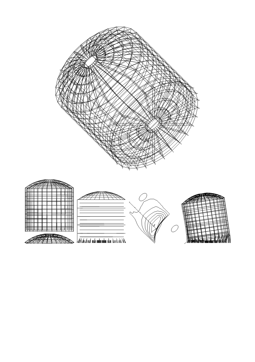
Figure 26. Model of the tank
Tank model substructures
Stress field at the moment
of failure
Deformation field at the
moment of failure
Figure 27. Elements of analysis, enabling the recovery of tank
3.10. Stress field in a pressure vessel
After several years of service, cracks were detected in a pressure vessel exposed to
internal pressure of 30 bar and temperature 200°C. The vessel, diamter
D
= 2000 mm,
height
H
= 6000 mm, and wall thicknes
t
= 24 mm, has been used for coal drying in the
company plant “Kolubara prerada” in Lazarevac. Stress analysis has been requested for
the analysis of crack origin. It was found that an important part of strain energy is distrib-
uted in upper and lower parts of the shell (20.1% + 39.2% = 69.3%) and in upper (20.1%)
and lower cupola (8.6%). Membrane stress is dominant (90.4%): in upper cupola 15.8%,
in upper part of shell 24%; in lower part 19.2%; and in supports 27.7%. The computation
showed bad stress distribution and corresponding poor behaviour of the pressure vessel.
290