


 292 / 392

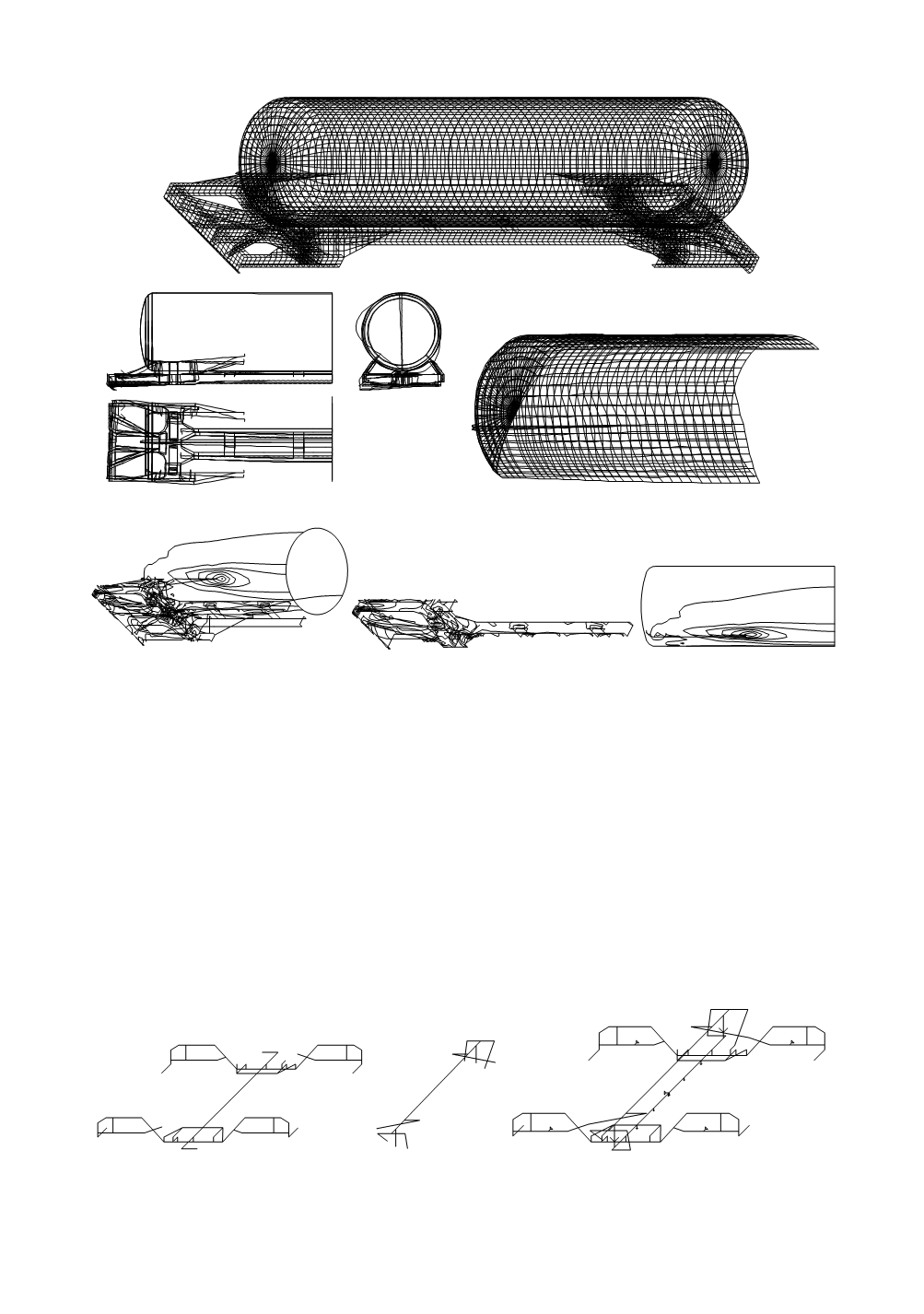
Figure 21. Computational models for tank car
Stress field of tank,
0–20 kN/cm
2
, step 2
Stress field of the lower bed,
0–20 kN/cm
2
, step 2
Stress field of the tank,
0–14 kN/cm
2
, step 2
Figure 22. Tank deformations in the moment of crash (left) and stress fields
The assumed load for calculation is the impact force of 600 kN on the tank car buffer.
Equivalent maximum stress in the crash was of modest value, 20 kN/cm
2
. Based on stress
and strain fields, and on load distribution and strain energy, it is possible to conclude that
the most important part of impact-energy was acquired by the car buffer. Nevertheless,
compressed elements and elements of bed could lose geometrical stability. Based on
previous consideration it was concluded that further tank exploitation is feasible.
3.8. Analysis of the behaviour of bogies on the train composition JZ 412-416
After several years of service, the electric-motor driven train composition JZ 412-416
(ŽTP Beograd), and the electric locomotives 441 and 461, and their bogies, exhibited
some unfavourable behaviour.
The structure of the bogies consists of several parts as shown in Fig. 23.
Frame, primary suspension and
pull-bar
Cradle and secon-
dary suspension
Model, loading, and supports of the bogie
Figure 23. Models of bogie compositions
288