
311
being on the order of magnitude comparable with the interatomic distances in silicon
carbide.
A new model, Discrete Fractal Fracture Mechanics (DFFM), is proposed here.
2. PRELIMINARIES. CLASSIC COHESIVE CRACK MODEL
When a cohesive model is designed, the length of the physical crack
c
is extended by
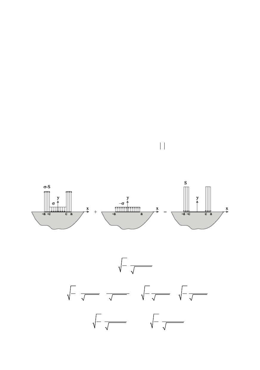
an adding the cohesive zones at both ends of the crack (Fig. 1). Within these zones the
restraining stress
S
counteracts the separation process. If the length of each cohesive zone
is
R
, then the half-length of the extended crack becomes
a
=
c
+
R
. In order to solve the
pertinent mixed boundary value problem one needs to assume the following distribution
of pressure applied along the surface of the extended crack
,0
( )
,
x c
p x
S c x a
σ
σ
≤ ≤
⎧
= ⎨ − ≤ ≤
⎩
(1)
This is later superposed with the uniform tension
p(x)
= -
σ
thus generating a stress-
free crack with two cohesive zones, in which the
S
-stress is present, Fig. 1. The second
boundary condition is expressed in terms of the displacement component
u
y
, which is set
equal zero along the symmetry axis outside the crack for
x a
≤
. The resulting solution is
the familiar stress field, which in the vicinity of the crack tip contains the dominant term
controlled by the stress intensity factor. This is the singular term, and it will be subject to
annihilation. Such requirement of disappearance of the singular term is know as the
“finiteness condition”.
Figure 1: The distribution of pressure applied along the surface of the extended crack
Before proceed to set up such condition for the crack given in Fig. 1,
K
-factors
associated with stresses
σ
and
S
should be evaluated. The well-known LEFM expression
2 2
0
( )
2
a
I
a p x
K
dx
a x
π
=
−
∫
(2)
is substitute (1) for the pressure
p
(
x
) to obtain the stress intensity factor for cohesive crack
0
0
2
2
2
2
2
2
2
2
(
)
2
2
2
c
a
a
a
c
c
TOT
a
dx
S dx
a dx
a Sdx
K
a x
a x
a x
a x
σ
σ
σ
π
π
π
∫
∫
∫
∫
⎧
− ⎫
⎪ =
+
=
−
⎨
⎬
−
−
−
−
⎭
⎪⎩
(3)
It is seen that both
σ
and
S
contribute to the total stress intensity factor. Notating as
2 2
2 2
0
2
2
a
a
S
c
a
dx
a Sdx
K
K
a x
a x
σ
σ
π
π
=
=
−
−
∫
∫
(4)
the Eq. (3) is rewritten as follows


