


 260 / 352

256
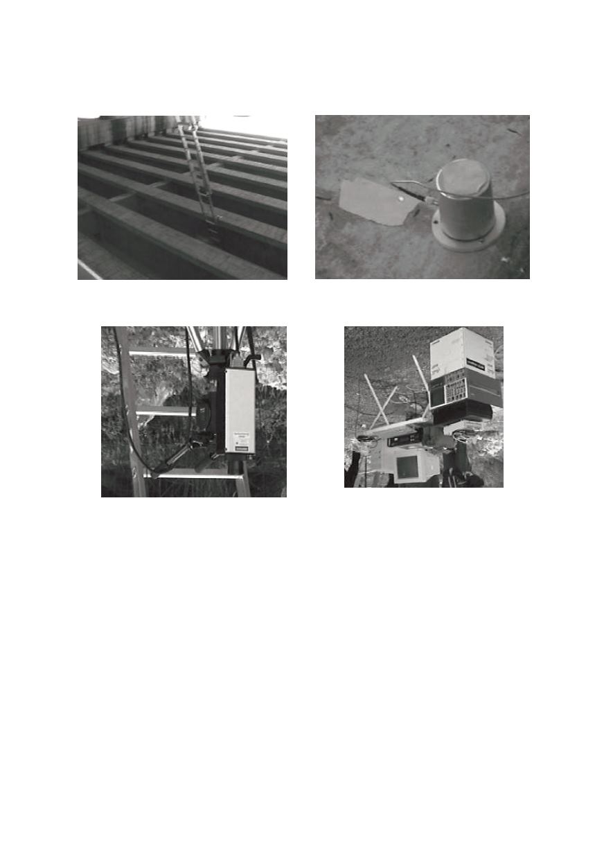
Figure 15 shows the measurement point for LDV as well for the accelerometer. The
measurement head and the entire LDV measurement system are shown in Fig. 16 /19/.
LDV head must be mounted on a stable holder not connected with a structure.
Figure 14: The lower deck of the bridge,
possible location for displacement measurement
Figure 15: The measurement point /19/
Figure 16: LDV measurement head (left) and LDV measurement chain (right) /19/
The analytical solution of bridge dynamic response under moving loads is complex
task, affected by many factors /20/. The basic geometry of the model is given in Fig. 17.
The length of the beam is
l
and a moving harmonic force
P(t)
is assumed with constant
velocity
V
0
. The solutions for the midpoint displacement depend on
Ω
- the frequencies
of the exciting force
P(t)
. Three cases are considered (Fig. 18):
Ω
lower than the first
beam resonance frequency (a), equal to it (b), and higher than it (c).
In Fig. 19 two direct measurements by LDV and accelerometer, showing variations of
displacement vs. time (up), its second derivative, a measure of the acceleration (middle)
and accelerometer signal (down). The accelerometer signal also follows variations of the
displacement and its second derivative, but LDV signals are more clear and useful/20/.
4.2. Electronic speckle pattern interferometry (ESPI)
While laser interferometer measures only one point at time, electronic speckle pattern
interferometry (ESPI) laser allows taking snapshot of vibrations of complete 2-D plane
and immediately shows the result of huge area as an image /21/. The disadvantage is that
the system is large and heavy, applicable only in the laboratory. The ESPI system produ-
ces two short flashes immediately after each other, records these diffractions by a CCD